Information about Electronics: January 2019

Sunday, January 27, 2019

Circuits & Chips


Information about Electronics ;
In this blog I will fully describe about integrated circuits and its types which are commonly used.
Integrated Circuits & Chips;
An integrated circuit or monolithic integrated circuit is a set of electronic circuits on one small flat piece of semiconductor material, normally silicon.
Commonly used integrated circuits;
Thousands of different types of integrated circuits (ICs) are available for electronic devices. Most of these were designed for very specific applications. However, many integrated circuits have been designed for general-purpose use and so are used in a wide variety of circuits.
As its name implies, the 555 is a timer circuit. The timing interval is controlled by an external resistor/capacitor (RC) network. In other words, by carefully choosing the values for the resistors and capacitors, you can vary the timing duration.

The 555 can be configured in several different ways. In one configuration (called mono stable), it works like an egg timer: You set it, and then it goes off after a certain period of time has elapsed. In a different configuration (called a stable), it works like a metronome, triggering pulses at regular intervals.

Besides the basic 555 chip, which comes in an 8-pin DIP package, you can also get a 556 dual timer, which contains two independent 555 timers in a single 14-pin DIP package. Because many common circuits call for two 555 timers working together, the 556 package is very popular.

Circuit diagram;

741 AND LM324 OP-AMPS;
An op-amp is a special type of amplifier circuit that has many applications throughout electronics. Although there are many different types of op-amp circuits, the 741 and LM324 are the most common.
The 741 is a single op-amp circuit in an eight-pin DIP package. It was first introduced in 1968 and is still one of the most widely used integrated circuits ever made. The 741 is one of those ICs that require both positive and negative voltage.

The LM324 was introduced in 1972. It consists of four separate op-amp circuits in a single 14-pin DIP package. Unlike the 741, the LM324 doesn’t require separate negative and positive voltage supplies.
Circuit diagram;


78XX VOLTAGE REGULATORS;
The 78xx is a family of simple voltage regulator integrated circuits. A voltage regulator is a circuit that accepts an input voltage that can vary within a certain range and produces an output voltage that is a constant value, regardless of fluctuations in the input voltage.

The xx in 78xx represents the actual voltage regulated by the chip. For example, a 7805 produces a 5 V output. The input voltage must be at least a couple of volts over the output voltage, and can be as high as 35 V.

Circuit diagram;


74XX LOGIC FAMILY
One of the primary uses for integrated circuits is for digital electronics, and the 74xx is one of the oldest and still most widely used families of digital integrated circuits. The 74xx family includes a wide variety of chips that provide basic building blocks for digital circuits. You won’t find complete microprocessors in the 74xx family. But you will find circuits such as logic gates, flip-flops, counters, buffers, and others.


Thursday, January 24, 2019

Capacitor


Information about Electronics;
     In this blog I will be describe about capacitor. Its types and features.
Capacitors;
A capacitor is a passive two-terminal electronic component that stores electrical energy in an electric field. The effect of a capacitor is known as capacitance.

Types of capacitor;
Capacitors are used in virtually every electronics circuit that is built today. Capacitors are manufactured in their millions each day, but there are several different capacitor types that are available.
Ceramic capacitor:   As the name indicates, this type of capacitor gains its name from the fact that it uses a ceramic dielectric. This gives the many properties including a low loss factor, and a reasonable level of stability, but this depends upon the exact type of ceramic used. Ceramic dielectrics do not give as high a level of capacitance per unit volume as some types of capacitor and as a result ceramic capacitors typically range in value from a few Pico farads up to values around 0.1 µF.

Electrolytic capacitor:   This type of capacitor is the most popular leaded type for values greater than about 1 microfarad, having the one of the highest levels of capacitance for a given volume. This type of capacitor is constructed using two thin films of aluminium foil, one layer being covered with an oxide layer as an insulator. An electrolyte-soaked paper sheet is placed between them and then the two plates are wound around on one another and then placed into a can.

Plastic film capacitors:   There are two main formats for the construction of plastic film capacitors:
Metallized film:   In this type of film capacitor the plastic film has a very thin layer of metallization deposited into the film. This metallization is connected to the relevant connection on one side of the capacitor or the other.


Film foil:   This form of film capacitor has two metal foil electrodes that are separated by the plastic film. The terminals are connected to the end-faces of the electrodes by means of welding or soldering.

Tantalum:   Ordinary aluminum electrolytic capacitors are rather large for many uses. In applications where size is of importance tantalum capacitors may be used. These are much smaller than the aluminum electrolytic and instead of using a film of oxide on aluminum they us a film of oxide on tantalum. They do not normally have high working voltages, 35V is normally the maximum, and some even have values of only a volt or so.

Silver Mica:   Silver mica capacitors are manufactured by plating silver electrodes directly on to the mica film dielectric. To achieve the required capacitance, several layers are used. Wires for the connections are added and then the whole assembly is encapsulated. The values of silver mica capacitors range in value from a few Pico farads up to two or three thousand Pico farads.

Super cap;   Super capacitors with capacitance levels of a Farad or more are now becoming more commonplace. These super capacitors are generally used for applications like memory hold up and the like.


Wednesday, January 23, 2019

Inductor


Information about Electronics;
In this blog I will be describe Inductor types and features.
Inductor;
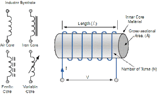
An inductor, also called a coil, choke, or reactor, is a passive two-terminal electrical component that stores energy in a magnetic field when electric current flows through it. An inductor typically consists of an insulated wire wound into a coil around a core.

Inductor types based on core;
There are different types of inductors. Depending on their material type they are basically categorized as follows,
Air Core Inductor;

    Ceramic core inductors are referred as “Air core inductors”. Ceramic is the most commonly used material for inductor cores. Ceramic has very low thermal co-efficient of expansion, so even for a range of operating temperatures the stability of the inductor’s inductance is high. Since ceramic has no magnetic properties, there is no increase in the permeability value due to the core material.

Iron Core Inductor;
     In the areas where low space inductors are in need then these iron core inductors are best option. These inductors have high power and high inductance value but limited in high frequency capacity. These are applicable in audio equipment’s. When compared with other core indictors these have very limited applications.

Ferrite Core Inductor;
Ferrites are mainly two types they are soft ferrites and hard ferrites. These are classified according to the magnetic coercively. Ferrite is also referred as ferromagnetic material. They exhibit magnetic properties. They consist of mixed metal oxide of iron and other elements to form crystalline structures . The general composition of ferrites is XFe2O4. Where X represents transition materials. Mostly easily magnetized material combinations are used such as manganese and zinc (MnZn), nickel and zinc (niZn).


Soft Ferrite;
These materials will have the ability to reverse their polarity of their magnetization without any particular amount of energy needed to reverse the magnetic polarity.
Hard Ferrite;
These are also called as permanent magnets. These will keep the polarity of the magnetization even after removing the magnetic field.
Ferrite core inductor will help to improve the performance of the inductor by increasing the permeability of the coil which leads to increase the value of the inductance. The level of the permeability of the ferrite core used within the inductors will depend on the ferrite material. This permeability level ranges from 20 to 15,000 according to the material of ferrite.


Iron Powder Inductor;
These are formed from very fine particles with insulated particles of highly pure iron powder. This type of inductor contains nearly 100% iron only. It gives us a solid looking core when this iron 
power is compressed under very high pressure and mixed with a binder such as epoxy or phenolic. By this action iron powder forms like a magnetic solid structure which consists of distributed air gap.

Laminated Core Inductor;
These core materials are formed by arranging many number of laminations on top of each other. These laminations may be made up of different materials and with different thicknesses. So this construction has more flexibility. These laminations are made up of steel with insulating material between them.

These are arranged parallel to the field to avoid eddy current losses between the laminations. These are used in low frequency detectors. They have high power levels so, they are mostly used at power filtering devices for excitation frequencies above several KHz.

Bobbin based inductor;
These are wounded on cylindrical bobbin so these are named as bobbin based inductors. These are mainly used for mounting on printed circuit boards.

It consist of two types of leads they are axial lead and radial lead. Axial lead means lead exits from both sides of the core for horizontal mounting on PC board. Radial lead means lead exits from both sides of the core for vertical mounting on PC board.


Multi-layer Ceramic Inductors;
The name itself indicates that it consist of multi layers. Simply by adding additional layers of coiled wire that is wound around the central core to the inductor gives multi-layer inductor. Generally for more number of turns in a wire, the inductance is also more.

Film Inductor;
These uses a film of conductor on base material. Thus according to the requirement this film is shaped for conductor application. Film inductors in thin size are suitable for DC to DC converters that serve as power supplies in smart phones and mobile devices.

Variable Inductor;
It is formed by moving the magnetic core in and outside of the inductor windings. By this magnetic core we can adjust the inductance value. When we consider a ferrite core inductor, by moving its core inside and outside on which the coil is wounded, variable ferrite core inductor can be formed.

Coupled Inductors
The two conductors connected by electromagnetic induction are generally referred as coupled inductors. We already seen that whenever the AC current is flowing in one inductor produces voltage in second inductor gives us mutual inductance phenomenon.

Molded inductors;

These inductors or molded by plastic or ceramic insulators. These are typically available in bar and cylindrical shapes with wide option of windings.

Monday, January 21, 2019

Transistor

Information about Electronics;
In this blog I will be describe about Transistor, It’s types and their features.
Transistor;
A transistor is a semiconductor device used to amplify or switch electronic signals and electrical power. It is composed of semiconductor material usually with at least three terminals for connection to an external circuit.


Different Types of Transistors;
We can say that a transistor is the combination of two diodes it is a connected back to back. There are so many types of transistors 
and they each vary in their characteristics and each has their possess advantages and disadvantages. Some types of transistors are used mostly for switching applications. Others can be used for both switching and amplification. Still other transistors are in a specialty group all of their own, such as phototransistors
Transistor Symbol;

Bipolar Junction Transistor (BJT)
Bipolar Junction Transistors are transistors which are built up of 3 regions, the base, the collector, and the emitter. Bipolar Junction transistors, different FET transistors, are current-controlled devices. A small current entering in the base region of the transistor causes a much larger current flow from the emitter to the collector region. Bipolar junction transistors come in two major types, NPN and PNP. A NPN transistor is one in which the majority current carrier are electrons. Electron flowing from the emitter to the collector forms the base of the majority of current flow through the transistor. The further types of charge, holes, are a minority. PNP transistors are the opposite. In PNP transistors, the majority current carrier is holes.

Field Effect Transistor;
Field Effect Transistors are made up of 3 regions, a gate, a source, and a drain. Different bipolar transistors, FETs are voltage-controlled devices. A voltage placed at the gate controls current flow from the source to the drain of the transistor. Field Effect transistors have a very high input impedance, from several mega ohms (MΩ) of resistance to much, much larger values. This high input impedance causes them to have very little current run through them. (According to ohm’s law, current is inversely affected by the value of the impedance of the circuit. If the impedance is high, the current is very low.) So FETs both draw very little current from a circuit’s power source.

Heterojunction Bipolar Transistor (HBT);
AlgaAs/GaAs heterojunction bipolar transistors (HBTs) are used for digital and analog microwave applications with frequencies as high as Ku band. HBTs can supply faster switching speeds than silicon bipolar transistors mostly because of reduced base resistance and collector-to-substrate capacitance. HBT processing requires less demanding lithography than GaAs FETs, therefore, HBTs can priceless to fabricate and can provide better lithographic yield.

Darlington Transistor
A Darlington transistor sometimes called as a “Darlington pair” is a transistor circuit that is made from two transistors. Sidney Darlington invented it. It is like a transistor, but it has much higher ability to gain current. The circuit can be made from two discrete transistors or it can be inside an integrated circuit. The hfe parameter with a Darlington transistor is every transistors hfe multiplied mutually. The circuit is helpful in audio amplifiers or in a probe that measures very small current that goes through the water. It is so sensitive that it can pick up the current in the skin. If you connect it to a piece of metal, you can build a touch-sensitive button.


 Schottky Transistor;
A Schottky transistor is a combination of a transistor and a Schottky diode that prevents the transistor from saturating by diverting the extreme input current. It is also called a Schottky-clamped transistor.

Multiple-Emitter Transistor;
A multiple-emitter transistor is specialize bipolar transistor frequently used as the inputs of transistor transistor logic (TTL) NAND logic gates. Input signals are applied to the emitters. Collector current stops flowing simply, if all emitters are driven by the logical high voltage, thus performing a NAND logical process using a single transistor. Multiple-emitter transistors replace diodes of DTL and agree to reduction of switching time and power dissipation.


Dual Gate MOSFET
One form of MOSFET that is a particularly popular in several RF applications is the dual gate MOSFET. The dual gate MOSFET is used in many RF and other applications where two control gatesare required in series. The dual gate MOSFET is fundamentally a form of MOSFET where, two gates are made-up along the length of the channel one after the other.


Junction FET Transistor;
The Junction Field Effect Transistor (JUGFET or JFET) has no PN-junctions but in its place has a narrow part of high resistivity semiconductor material forming a “Channel” of either N-type or P-type silicon for the majority carriers to flow through with two ohmic electrical connections at either end normally called the Drain and the Source respectively. There are a two basic configurations of junction field effect transistor, the N-channel JFET and the P-channel JFET. The N-channel JFET’s channel is doped with donor impurities meaning that the flow of current through the channel is negative (hence the term N-channel) in the form of electrons.

Avalanche Transistor;
An avalanche transistor is a bipolar junction transistor designed for process in the region of its collector-current/collector-to-emitter voltage characteristics beyond the collector-to-emitter breakdown voltage, called avalanche breakdown region. This region is characterized by the avalanche breakdown, an occurrence similar to Townsend discharge for gases, and negative differential resistance. Operation in the avalanche breakdown region is called avalanche-mode operation: it gives avalanche transistors the capability to switch very high currents with less than a nanosecond rise and fall times (transition times).

Diffusion Transistor;
A diffusion transistor is a bipolar junction transistor (BJT) formed by diffusing dopants into a semiconductor substrate. The diffusion process was implemented later than the alloy junction and grown junction processes for making BJTs. Bell Labs developed the first prototype diffusion transistors in 1954. The original diffusion transistors were diffused-base transistors. These transistors still had alloy emitters and sometimes alloy collectors like the earlier alloy-junction transistors. Only the base was diffused into the substrate. Sometimes the substrate produced the collector, but in transistors like Philco’s micro alloy diffused transistors the substrate was the bulk of the base.


Diodes

Information about Electronics;
In this blog I will be describe Diodes its types and features.
Diodes;
                    A diode is an electrical device allowing current to move through it in one direction with far greater ease than in the other. The most common kind of diode in modern circuit design is the semiconductor diode, although other diode technologies exist.

Types of diodes;
There are several types of diodes are available for use in electronics design, namely; a Backward diode, BARITT diode, Gunn Diode, Laser diode, Light emitting diodes, Photodiode, PIN diode, PN Junction, Schottky diodes, Step recovery diode, Tunnel diode, Varactor diode and a Zener diode.
Backward diode;
This type of diode is also called the back diode, and it is not widely used. The backward diode is a PN-junction diode that is similar to the tunnel diode in its process. It finds a few special applications where its specific properties can be used.

BARITT Diode;
The short term of this diode Barrier Injection Transit Time diode is BARITT diode. It is applicable in microwave applications and allows many comparisons to the more widely used IMPATT diode.

Gunn Diode;
Gunn diode is a PN junction diode, this sort of diode is a semiconductor device that has two terminals. Generally, it is used for producing microwave signals.

Laser Diode;
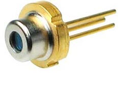
The laser diode is not the similar as the ordinary LED (light emitting diode) because it generates coherent light. These diodes are extensively used in many applications like DVDs, CD drives and laser light pointers for PPTs. Although these diodes are inexpensive than other types of laser generator, they are much more expensive than LEDs.

Light Emitting Diode;
The term LED stands for light emitting diode, is one of the most standard types of the diode. When the diode is connected in forwarding bias, then the current flows through the junction and generates the light. There are also many new LED developments are changing they are LEDs and OLEDs.

Photodiode;
The photodiode is used to detect light. It is found that when light strikes a PN-junction it can create electrons and holes. Typically, photodiodes operate under reverse bias condition where even a small amount of flow of current resulting from the light can be simply noticed. These diodes can also be used to produce electricity.

PIN Diode;
This type of diode is characterized by its construction. It has the standard P-type & N-type regions, but the area between the two regions namely intrinsic semiconductor has no doping. The region of the intrinsic semiconductor has the effect of increasing the area of the depletion region which can be beneficial for switching applications.

PN Junction Diode;
The standard PN junction may be thought of as the normal or standard type of diode in use today. These diodes can come as small signal types for use in RF (radio frequency), or other low current applications which may be called as signal diodes. Other types may be planned for high voltage and high current applications and are normally named rectifier diodes.

Schottky Diode;
The Schottky diode has a lower forward voltage drop than ordinary Si PN-junction diodes. At low currents, the voltage drop may be between 0.15 & 0.4 volts as opposed to 0.6 volts for a Si diode. To attain this performance they are designed in a different way to compare with normal diodes having a metal to semiconductor contact.

Step Recovery Diode;
A step recovery diode is a type of microwave diode used to generate pulses at very HF (high frequencies). These diodes depend on the diode which has a very fast turn-off characteristic for their operation.

Tunnel Diode
The tunnel diode is used for microwave applications where its performance surpassed that of other devices of the day.

Zener Diode;
The Zener diode is used to provide a stable reference voltage. As a result, it is used in vast amounts. It works under reverse bias condition and found that when a particular voltage is reached it breaks down. If the flow of current is limited by a resistor, it activates a stable voltage to be generated. This type of diode is widely used to offer a reference voltage in power supplies.